
Sensicomm LLC - DSP design services.
Algorithms, software and hardware for sensors, signal processing, and communications.Home About Contact Publications Projects Downloads Sitemap Blog
A combination of analog and digital blocks is used to form a speech synthesizer. Parameter tables in ROM drive the synthesizer to generate selected words or phrases. It can be integrated into other PSoC-based products to add a low-cost speech output capability. Talking clocks or voltmeters are examples of possible uses.
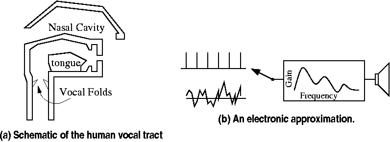
Figure 1 Speech synthesis using a model of the vocal tract.
Voice output is a useful feature for situations where an operator is unable to use a graphic display. An example would be a talking voltmeter, where the user can focus on the device under test instead of glancing back and forth to the meter's visual display.
Conventional implementations use a digital signal processor (DSP) or dedicated synthesis chip to implement voice synthesis or playback of stored audio. For systems that already include a PSoC this added complexity can be avoided: some analog and digital blocks can be configured to synthesize intelligible speech with zero added external components (except for a few wires).
The design uses 6 of the 8 available switched-capacitor analog blocks and 3 digital blocks. The remaining analog and digital blocks are available for other functions. Alternatively, all of the analog and digital blocks could be reconfigured to perform other functions when the chip is not talking.
This note describes a reference implementation that speaks the phrases "Hello, I am a PSoC; I do amazing things" and "the temperature is seventy- three degrees." Additional words and phrases can be added as required by a specific application.
The other parts of the vocal tract (mouth, tongue, teeth, etc) become a time-varying resonant structure that shapes the spectrum of the speech to form the desired sounds. A cascade of second-order bandpass filter sections provides a good model of the vocal tract functions.
So, to make speech we need a pulse source, a noise source, a pulse/noise switch, and some bandpass filters. Standard PSoC blocks can provide all these functions.
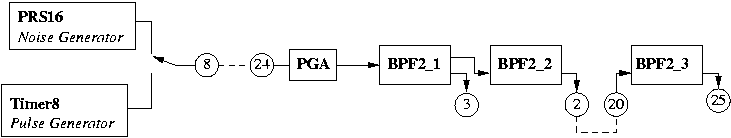
Figure 2 PSoC blocks arranged to form a speech synthesizer.
The PSoC implementation uses the following blocks, arranged as shown in Figure 2:
A mux is also required, to connect either the PRS output or the timer output to the input of the VGA. The standard MUX block could be used to provide this capability, but a simpler approach is to do it within the digital infrastructure. The PRS output is directed to the "Row 0 Out 0" internal bus, and the Timer output is directed to the "Row 0 Out 1" bus. The Row Digital Interconnect (RDI) contains a lookup table (LUT) that can combine two inputs into a single output. In the configuration used here, the PRS output is the A input to LUT 0 and the Timer output is the B input to it. The desired output is selected by writing 3 (for A) or 5 (for B) to the 4 lsb's of the RDI0LT0 register.
Most of the interconnections between blocks are made using the internal connection paths. The connection between the multiplexed output of the digital blocks and the VGA requires the use of external pins, as does the connection from BPF2_2's output to BPF2_3's input.
The PSoC BPF2 blocks each require a pair of switched-capacitor blocks that are horizontally or vertically adjacent. This design uses the horzontal configuration for the first two, but a vertical configuration for BPF2_3. The use of a vertical configuration leaves both unused analog blocks in the same column, so they are not required to use the same analog clock that the filters use. This provides more flexibility in assigning additional functions to these unused blocks.
The sample code is written for the PSoC Invention Board. A photo of the prototype configuration used for software development and testing is shown in Figure 3. Essential input and output connections for the board are listed in Table 1.
The synthesized output is available at the output of BPF2_3 on pin 25. A Realistic SA-10 audio amplifier was used to monitor the audio during development. The output level is typically 1-2 volts peak-to-peak, which is suitable for direct connection to the line input of most audio amplifiers (a DC blocking capacitor may be required with some). An LM386 or a more modern class D amplifier could be used to drive a speaker directly, if desired.
The demonstration software implements a loop that periodicly updates the parameters of the PSoC blocks. Code in main.asm performs the initialization and configuration of the PSoC blocks, sets the parameters to reasonable default values, and then enters a loop that plays out a test message. Routine vtable.asm contains the code to step through a table of parameters and update the PSoC blocks. Various include files contain the parameter sequences for the message to be spoken. These files are generated externally.
The following fragment of code plays a message:
	call _vtableset0

call _sayphrase
Routine _vtableset0 sets a pointer to the beginning
of the message to be spoken:
	_vtableset0:

	mov [vtablea],>_vtable0 ; A is the msb's.

	mov [vtablex],<_vtable0 ; X is the lsb's.

	ret
Other routines (_vtableset1, etc.) are similarly
used to select other messages to be spoken.
Routine _sayphrase
implements loop containing a delay to the start of the next update
interval, followed by an update to the block parameters.
	_sayphrase:

	call delay10ms

	call _updatefilt

	cmp A,0  ; If updatefilt()=0, continue.

	jz _sayphrase

	ret
Routine _updatefilt reads parameters from the
ROM table and updates the settings of the analog and digital
blocks using the standard PSoC routines. It steps through the
ROM table using routine _vtablenext
	_vtablenext: ; Return the next byte from

	; a ROM table in A. X destroyed.

	mov a,[vtablea]  ; Get the address.

	mov x,[vtablex]  ;

	romx ; Load the byte at rom[(a<<8)+x]

	add [vtablex],1  ; Increment.

	adc [vtablea],0  ;

	ret
The parameters stored in the ROM tables are the pitch counter repeat value, VGA gain setting, and the capacitor values for the filter blocks. The MUX selection value is derived from the pitch value.
The gain and capacitor values are determined by analysis of a recorded sample of the desired phrase. Bandpass center frequency and Q values can be determined using speech analysis techniques described in texts such as Speech Communication - Human and Machine, by D. O'Shaughnessy. These can then be converted to capacitor values using the equations from the bandpass filter documentation.
This PSoC configuration and its software provide a simple and low-cost way to add voice output to various devices. As with all vocoders, the output is highly intelligible, with a somewhat "robot-like" quality. Enhancements that can be added in the future include control of the playback rate or on-the-fly modification of the pitch and volume for emphasis or other special effects.
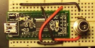
Figure 3 Prototype on a solderless breadboard.
Table 1 Connections to the prototyping board.
| Output pin | Input pin | Description |
| 8 | 24 | Pitch pulses or Pseudorandom noise to VGA input |
| 2 | 20 | BPF2_2 output to BPF2_3 input |
| 25 | - | Output speech |
$Id: psoc.shtml,v 1.2 2016/02/16 12:29:00 jrothwei Exp jrothwei $